-->

Ads Bidvertiser

Thursday, December 18, 2008

Hot Rods of the 1940's


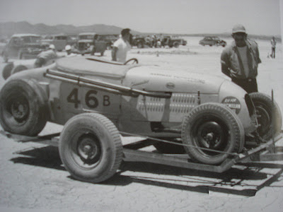
Neat stuff here. These are photos of dry lakes and dual-purpose roadsters. Notice the inherent beauty in these individual builds, and the differences. And also notice they are all the same car...'26 and '27 Model T Roadsters. I especially like the little black one in the background of the last picture. Very genuine, very little! And very "hot rod" for that time.

Also, look at the green beauty with the gal waiting inside. Windshield and lights are just removed as it waits for the opportunity to make a speed trial. Little '40 caps on white walls front and back-very hard to find in the WWII era. Notice the fronts are motorcycle tires, white-walled on both sides.

I like these little beetle bugs. I like the history of their making. I like how they look. These aren't overdone. These aren't Bling Bling. Gosh, they don't look mean, either. They look like jalopy projects built by experimenters, modifiers....but so fitting and proper. This is what real hot rods looked like, because these were...are... real hot rods.

Thanks to Don Montgomery and Robert Genat for the wonderful books I stole these pictures from. Want to learn about real hot rods? Read their books, as well as articles in The Rodder's Journal.

Sunday, December 14, 2008

Spreader Bar The Right Way!


Here's more completion on the little buggy car. Its the spreader bar- that little rod going from one frame horn to the other right at the front of the T-V8. This little abandoned project car had a spreader...but it was just wrong. The bar was about 2" diameter heavy tube welded to each frame horn, with the original mounting holes all welded shut. It was way too big, way too fake, and welded on. They aren't supposed to be welded! That is not how the early hot rods were done. They should be bolted on through the existing frame horn holes where the little splash apron originally would attach.

So I cut the oversize welded-on pipe off and drilled the original frame holes back out, pinpointing the location from the inside frame view. I then cut a piece of smaller tubing and welded nuts into large washers on the tubing's ends. The nuts were off centered in order to push where they would allow the spreader bar to sit: right at the front of the frame horns. After careful fitting, I welded up the assembly and bolted it on. Now that is how they are supposed to look.

Why am I so opinionated about the spreader bar, yet allow the car to appear old, weathered and unfinished? Well, it is old, weathered and unfinished. Just like it is supposed to be. Just like many a little jalopy bought and torn apart by eager boys after WWII, stripped of fenders and running boards and hopped up in the most literal and genuine sense.

Sheet Metal Brake


I'm still on the "make it yourself" thing. Well truly, I'm always on it. And this one is no different. The above pic shows my messy, tiny table where I use my standby vise (given to me years ago by my employer). And in the vise is my homemade sheet metal brake. I built this because I recently got Eastwood's shrinker/stretcher set, and I needed something to make nice straight bends to try out on the shrinker/stretcher. So I made this little 20" attempt at a brake, and it turned out fine. The steel is scraps I have around, and the handles are old ones from a broken drill press. This little thing works...hows that for post traumatic brain injury time? Woo Hoo! So now I can make window channel pieces and fender well strips out of sheet steel by simply making a straight bend on the brake, and then forming the proper radius or curve on the shrinker/stretcher. Man alive Jackson Five, I like doing this stuff...

Sunday, December 7, 2008

More progress...


Wiring diagram and harness is now officially done for the '27. And it was actually fun to do. I was forced to look at books and diagrams, to wrap wire leads, and to install everything neatly and safely. The battery has room only in the trunk, so I decided to use the remote solenoid as sort of the main junction block for positive voltage. I ran huge wire from the battery terminal through and under the body, and up to the firewall outside. The big wire was installed with good protection and lots of supports. During this project I quickly realized that the body needed final mounting before I could secure the wiring that passes under, through, around, etc., the body. And this became a rewarding but tedious project its self. I did not realize the body would flex and bend as much as it did while making body mounts and securing it to the frame. But soon it was done, after much spacing, adjusting, etc. And now I have all the wiring hooked up, tested and working right.

The picture above is the harness diagram I made. It shows how I wired the buggy and what choices I made. The headlights are Dietz-type 7" sealed beams and the rears are '39 Ford. The front has turn signal lights from a '68 Mopar, and the turn signal switch is an old Signal Stat 900 that doesn't come with an indicator light on the switch. (That is why it only had 6 wires, not seven like all the plans I saw explained).

And the best reward was the test drive(s). The little gauges are tachometer, oil pressure and water temp, nothing more. And the test drive got me quite excited as well as it tought me to adjust and tighten the rear 4-link setup I made. A rear end has a tendency to hinge up and down if the 4-link bars aren't tightened. I knew that....no really...! It's good I was able to see the reason the driveshaft kept getting closer to the floor (and fuel line!). Nowadays my new plan is to remember what is in mock-up stage and what is not. You see, I have too many untightened bolts!

Notice the old headlight switch- I used "PARK" setting for low beams, and "HEAD" for high beams. This way I don't have to install a brights switch.